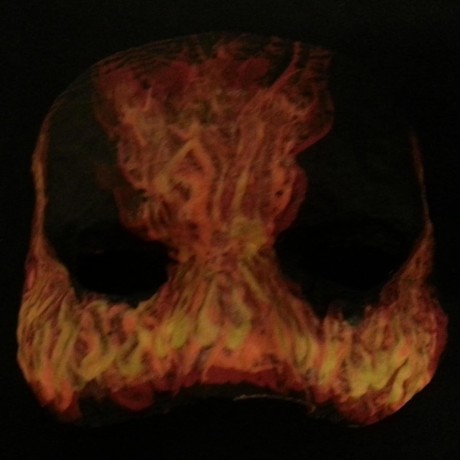
I still have no idea what I’m doing really. Just too determined to give up I guess, and it’s been such fun. Anyway I made a guitar pedal light switch cover. Still a lot of work to do, and every time I look at FreeCAD the wrong way, the model breaks, but it’s been a fun experience nonetheless.
On a side note, anybody have any idea why the face of the model is rough textured, while the foot switch on the lower half is flawless?

It appears that you need to get the nozzle closer to the print bed. You shouldn’t have gaps between the lines like the rough side. Also, check the slicer settings to make sure it’s doing several top layers/walls.
Please forgive my rudimentary knowledge here, but if it was a z height issue, wouldn’t it affect the bottom part of the print where it’s nice and smooth as well? I clean and level between every print, and the corners seem to be very snug at least using the paper method. It’s just enough clearance that I can still push and pull the paper without it catching on the nozzle
For one thing, the paper method only gets you so close. I find you actually have to watch your first layer go down and adjust that way. If you have a Prusa, there is a menu where you can make adjustments as it’s printing and it has a first layer calibration tool built in.
Second, check the slicer and see what it’s calling the very top layer vs what it’s calling the part that looks messed up. I’m willing to bet that the clean looking part is called top layer, whereas the messed up part isn’t. Prusa slicer ads additional material when it knows that it’s the very top of a print so that it looks better.
Either that, or is say you had a clog which caused under extension, but that may have worked out by the end of your print.
The paper method only ensures that you get the nozzle-to-bed distance reasonably consistent in all the places your printer checks it, to ensure that the bed is trammed, i.e. straight relative to the X and Y axes of the printer, or “level.” It doesn’t guarantee that your Z offset is actually correct to produce a good first layer, and depending on how your particular printer runs its bed leveling/Z offset program it may in fact guarantee that it is incorrect every time.
If you’re going to use some manner of gauge material (paper, one of those plastic cards, a feeler gauge), step 1 is to determine what, exactly, your printer does to set its Z offset and whether or not that’s taken into account when you’re sliding your piece of paper or whatever under the nozzle. Some printer firmwares further compound things by calling their Z offset adjustment program “bed leveling” when that’s not what it is. (My old Qidi was guilty of this. “Fast leveling” was actually just Z offset adjustment in the center of the build plate, and “Full leveling” was actually a four-points bed level check operation.)
Thanks, i’ll check those things. Sadly, I don’t (yet lol) have a Prusa, only an Ender 3 pro. According to Prusa slicer, it’s all top solid infill. Here is the STL file if anyone is more of an expert at prusa slicer than I. https://www.printables.com/model/700351-guitar-pedal-light-switch/files
How can you tell that OP hasn’t leveled their bed properly? You can’t see the bottom layer in their picture.
Not level, Z height. Z height shows as lines spaced too far apart. Could also be under-extruding.
Sure, on the first layer. We can’t see the first layer here, only the top layer, so it can’t be the z height.
As far as I know, z height affects all layers. Check out https://forum.prusa3d.com/forum/original-prusa-i3-mk3s-mk3-how-do-i-print-this-printing-help/rough-top-layer-surface-on-new-prints-after-recent-z-axis-calibration/ and see if that makes any sense.
This has happened to me before - a messed up z height will affect all layers because the squish isn’t there at any layer. You’ll always have that difference in height between the surface being built and the nozzle no matter what layer you’re on.
Skimming that post shows a lot of people saying that first layer doesn’t affect top layer. What is your definition of z height? We may have a definition issue on our hands here. To me, it means the distance between the nozzle and the bed on the first layer.
I’d be with you on the underextrusion though if the very top layer didn’t look so good. I would bet OP doesn’t have enough layers on top of the infill leading to an artifact that resembles underextrusion.
If you can get used to an open source tool like free cat, don’t let anyone here dissuade you from it. Something to be aware of with the closed source tools is that at any moment they can take them away. CAD tools like that are super expensive if there isn’t a free plan, and there’s every reason to believe that someday the free plan will go away.
I haven’t been able to wrap my head around freak out because just not that smart, but that doesn’t mean I don’t realize tinkercad can go away at any moment. It metaphorically keeps me up at night.
I think FreeCAD would win a lot more converts if it focused on usability. Fusion360 and Onshape are parametric modelers just like FreeCAD yet they’re way simpler, taskcentric and more forgiving tools to use.
The worst thing about FreeCAD is that it’s extremely unreliable. You click a wrong button and your work is gone.
Forgiving is the word for this - being able to undo mistakes and recover. I reckon FreeCAD would massively benefit from doing a complete feature freeze and focusing on usability for a couple of releases.
It’s not about being forgiving or not, FreeCAD is just ridiculously buggy. They are trying to do too many things at once and none of the things actually work in the end.
That mostly comes from not understanding what best practices are when using ANY 3D CAD. They all fail repeatedly and a lot more often than you think. It’s just that some fail more gracefully than others. And some will bite you for being sloppy with your procedures. FreeCAD will bite if you get careless.
But things are looking up. Since the formation of the non-profit Ondsel, there is now a coherent set of adults in the room mapping out a sensible pathway forward for FreeCAD. Their first order of business if fixing the topological naming issue that plagues FreeCAD. The changes have started and are expected to be completed in 3 releases. It’s going to take some time to do because of the changes needed to a chunk of the base code of FreeCAD. There are already some nice new features that have been added to the .22Dev releases for improved quality of life. And the UI is expected to be slowly changed over time as well. Though I personally hope they don’t turn it into the small child’s cartoon clown car UI of Fusion 360.
What slicer are you using?
Also was the clean part attached to the bed or do you have ironing turned in on the slicer?
I’m using Prusa slicer. I don’t think I have ironing turned on, but I’ll double check
Hey, I’m working on a guitar pedal. It is a multi-effects pedal based on a Pi Pico:
http://www.github.com/profdc9/GuitarPico
It will connect to a VGA monitor and have cool visual effects to go along the with the playing. So far I have implemented:
Delay, Room Echoes, Low Pass, High Pass, Bandpass, Wah Pedal, Phaser, Flanger, Distortion, Overdrive, and Ring Modulator.
The pedal can be programmed so that several effects are cascaded.
Congrats, and enjoy your new tools.
3D printing to me is still amazing; if you can think it, you can design it on a computer, and then you can make it real. Blows my mind to go from idea to real in just a few hours.
Did you turn layer ironing / smoothing on for the last layer not all top layers? Aside from smoothing modern slicers can also use more attractive patterns for top layers than zig zag such as hilbert.
It also looks like you might have underflow issues so maybe check your e-step setting on your printer to ensure you’re extruding proper amount of filament. There are articles that explain the process but you basically mark a reference point on the filament, e.g. 10cm away from where it enters the extruder, tell the printer to extrude 10cm, mark and measure how far away the mark is from where it’s meant to be. So if the filament moves 7cm when it should have 10cm then your e-steps need to be multiplied by 10/7.
FreeCad is a nice foss entry, but it tends to get arcane the further you dive. If you find fc stops doing what you need then try fusion 360. F360 is closed source and makes you save files in the cloud so it’s a birch that way, but about 10x easier to use.
F360 personal is limited to 10 saved designs, and I don’t know how expensive but a lot. I mean I use it but I wish I didn’t
10 saves that you can actively work on. You can toggle them between “editable” and “read only” at any time, so it’s a stupid nuisance but not really more than that.
At least it doesn’t force you to publish designs online like onshape does
I actually asked OnShape a question and have yet to hear from them. Due to what seems like very poor legal drafting, as best I can tell, they force the creators to agree to non-commercial usage, but then they just give EVERYONE ELSE a license to use the designs commercially. I think that either the public thing was a late addition to their business model, or they were just too lazy to distinguish between what THEY could do with other people’s designs and what random Joe Etsy could do. The email address listed on the Terms of Use to accept questions bounces back external emails, though. Nice.
I suspect that it’s a recent change- probably an attempt to build up a repository like thingiverse… only they figured, why bother with attracting content when you could just force it.
Basically, it’s now their models in the cloud. Their IP. Your work, your, uh “intellect”… their tool, and it’s now theirs.
True. Tbf. I like that I can easily share my things with my friends but dislike the forced online.
criticism of F360 is definitely fair game. i don’t like the forced online, and I don’t like they only support windows (cuz linux is scawry), and I the cut-down version has some fairly deep cuts in the utility. (I use FC for setting up the open foam problems and FEM studies. it actually works well for that.)
the 10 active files things is a stupid, stupid restriction to impose, though. like, i’m not even sure why they did. restricting access to FEM studies or generative design etc, yeah, that makes sense. (though I’d love it if they let me do local things, too… my computer can handle it…)
If fusion 360 doesn’t run natively on Linux, sadly I’m not interested. I haven’t run Windows on personal machines in many years.
Onshape is incredibly forgiving. Ran it on the browser on my laptop from 2011
What a shitty limitation though.
Same
I mean I just export my files to my drive and then the 20 file limitation is nonexistent
I used to recommend F360 for beginner but now I think Onshape is a better option.
Onshape is indeed quite easy to get the hang of. Only downside is that it doesn’t work that well with a shitty internet connection. So trying to finish a model between classes was definitely easier when I was still using f360.
Me again with unpopular approach, just pirate solidworks and enjoy the best CAD experience 😉
Avoid cloud based software. All of your work disappears when it gets shut down or if they just feel like deleting your files or closing your account for any reason they choose.
There are other open source CAD programs like SolveSpace, which many people consider to be easier than FreeCAD.
There is BRL-CAD which is quite capable if you don’t mind the 1980’s style GUI. There is also OpenSCAD if you like scripting instead of a point and click interface.Haven’t heard off solve space, will try it out
Solvespace is amazing, the interface is probably the most consistent among any CAD program. Unfortunately volumetric operations (Union, subtraction …) are kind of buggy sometimes.
Look at OpenSCAD too, if you have clumsy hands or tunnel syndrome or something.
It’s for drawing objects for printing with code, using primitives and CSG, and a very simple tool to use at that.
Did you print the foot switch upside down and then flip it? If so, how does its other side look?
I can’t tell how the surface quality is by the knobs.
Your “main” top surface looks like under-extrusion.
It’s all a single part, so that’s how it printed. I have a sneaking suspicion it’s because of how I did the steps in free CAD, not having a clue what I was doing, etc. before I pass any judgment, I’m going to print other files and see if the issue persists. I’m already planning to rebuild the entire thing in free CAD again, using what I’ve learned in the process
It’d be interesting to see what it looked like in the slicer, just in case it’s obvious there.
And yeah, each new FreeCAD project I do builds on what I’ve learned and it gets easier to get better results.
Here is a link to the STL, if you want to poke around. https://www.printables.com/model/700351-guitar-pedal-light-switch
One other thing that occurred to me is squish. Just like your first layer issues, the plastic on every layer needs something beneath it to squeeze against so it converts from a circular tube to a flat, wide oval. Maybe your slicing didn’t have enough support or infill in the main body as compare to the final top surface? You could try increasing the horizontal shells.
By the way, I assume you did not turn on ironing, because that could also affect the surfaces differently if one got ironed and the other didn’t for some reason.
Well we got another one hooked 😂
No idea why you’re having issues 3d printing. I’ve never heard of FreeCAD. But curious if you’ve ever tried Blender? It’s free, and really good for modeling stuff like this.
Blender is the last thing I would recommend to someone making functional parts like that. Fusion 360 is probably a more intuitive leap from FreeCAD, or OnShape, which I wish I had learned instead of Fusion in the first place.
I’ve been familiar with Blender for many years, at least by name, being a Linux nerd for probably half my life. Never really used it though, in truth I had to pick a cad software and that was available in the repositories lol. I do find a free CAD maddeningly frustrating to use though, so maybe I should check out blender too.
Blender is great for decorative/pretty stuff. CAD software is great for functional stuff as pointed out by others. It’s just so much easier to get accurate measurements and dimensions with CAD software compared to blender.
Yeah, Blender has two major limitations for mechanical-type parts:
One, it’s not parametric even with its CAD plugins, but whatever. If you’re only designing one part or a small assembly, you can manage without parameters, and the basic act of “make something” is often easier and more intuitive with a direct modeler.
Second, it’s editing meshes only. For 3D printing, that’s not really the end of the world, as Slicers only work with meshes anyway, but as you say it limits resolution and accuracy, and could mean you have a bad time if you wanted to get a better printer or leverage some other form of manufacturing. It’s not a perfect analogy, but it’s kind of like using Photoshop and only saving in JPG.
I would definitely give it a try, maybe a flavor of 3.6 since 4 just came out. But over the last 19 years it’s really had some major improvements and works really well for a free software (relatively bug free) for what it is. Best of luck on your 3D printing journey!
there are alot of tutorials for modelling with blender. Best thing is you now apply those skills toward other blender features if you want to. Also it auto updates with steam.
Blender, even with the CAD plug-in, does not have the dimensional precision required for real engineering modeling. The Blender UI is also even clunkier than FreeCAD in many ways.
Seems to be underextruded a bit.
Probably something to do with temperature or your nozzle being slightly clogged.
See if you have the setting for “ironing” turned on in your slicer.
Thanks, everyone seems to agree on the under extrusion bit, so that definitely seems like what it is. I’m pulling my hair out trying to figure out exactly what. I may look at the e steps next. Ironing is not turned on, and I just cleaned the nozzle.
Before you go through a bunch of calibration, I’d see if it happens with a different filament. Those black particles there are likely something with a higher melting point than the surrounding PLA, otherwise they’d “smear” during printing. I’m betting you’re hitting some intermittent clogs. See if the problem happens with a single color filament.
Thanks, I hadn’t considered what made the marble in this marble white. I noticed this with my previous filament as well. This was a dual color PLA with under extrusion issues. I still use the original plastic extruder, and I bought it second hand, so no idea how much wear is on that arm but it’s been in use for several years at least. I ordered an aluminum upgraded one and a filament dryer, and they should be here tomorrow. I’ll upgrade the extruder, dry the filament, and check esteps afterwards to see if that was my part of the under extrusion.

I don’t have a prusa, but can you calibrate E steps on that printer? That can definitely result in a nice looking first layer and following less-filled layers if it’s off.
That is absolutely the next thing on my list to do. It still has the all plastic extruder, and my all metal replacement arrives tomorrow. I figured no point in calibrating until I replace that
New Lemmy Post: One month ago, I didn’t really know what 3D printing was. Yesterday, I designed in FreeCAD my first model and printed it. What an amazing experience. (https://lemmy.world/post/10186306)
Tagging: #3dprinting(Replying in the OP of this thread (NOT THIS BOT!) will appear as a comment in the lemmy discussion.)
I am a FOSS bot. Check my README: https://github.com/db0/lemmy-tagginator/blob/main/README.md


